System Overview
This section will provide an overview of the system hardware, as well as a diagrammatic sketch of the system layout.
There are multiple ways in which the new byte addressable storage class memory (SCM)can be applied, and the different modes each have specific uses and user instructions associated with them. The various applications of the memory are summarised in the section Memory Modes.
Hardware
Login/Management Node:
- 2x Xeon Platinum 8260 24C 2.4GHz
- 6x 16GB DRAM
- 2x 256GB NVDIMM
- 3x SATA-SSD ~2TB
Compute Node:
- 2x Xeon Platinum 8260 24C 2.4GHz
- 12x 16GB DRAM
- 12x 256GB NVDIMM
- No internal SSD/HDD: remote boot
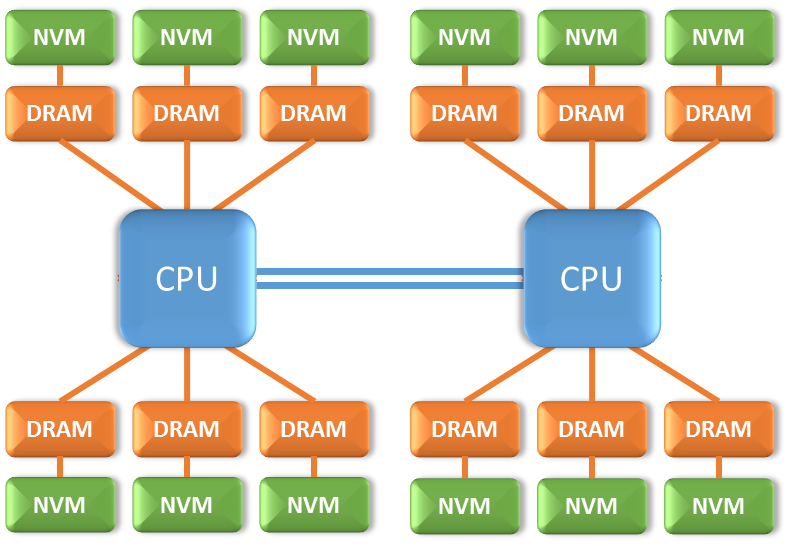
Figure 1 The structure of the Compute Nodes: two Cascade Lake CPUs, combining DRAM and NVRAM in each memory channel. DIMMs sharing the same channel to the CPU will also share the channel’s bandwidth.
Memory Modes
In general the SCM can operate in a variety of modes: as an extension of traditional DRAM, as storage, and as a new class of persistent memory (NVRAM). This means that in the NextgenIO system, the SCM can be applied in a number of configurations.
The SCM is included in the system in the form of NVRAM DIMMs (NVDIMMs), and is always combined with DRAM DIMMs (see Figure 1). The difference between configurations lies in the modes in which the NVRAM is applied. At the platform level, nodes can be booted in two different modes. Switching between platform modes requires a reboot of the nodes.
At the NVDIMM level the SCM can be partitioned, reserving sections of the SCM to operate in one of two modes. This implies that different memory ‘reservations’ can exist in different partitions on the same NVDIMM simultaneously. These partitions are managed by the memory controller. The two modes are ‘memory mode’ and ‘App Direct’ mode respectively. The choice of mode influences how the SCM can be accessed in the different platform modes.
A more abstract level of access is made possible through the use of namespaces. Namespaces are subdivisions of Memory Pools, which are BIOS mapped physical memory ranges. The Memory Pools are classed as either volatile or persistent, and switching between the two requires rebooting the node. Namespaces, on the other hand, can be reallocated within existing Memory Pools without a reboot. Namespaces can only be created on SCM reserved in the ‘App Direct’ mode.
The choice of platform mode impacts the usage of the different reserved partitions on the NVDIMM. The platform level modes are:
- Memory mode: In Memory mode, also known as two-level memory mode (2LM), the byte-addressable persistent memory is transparent to applications and represents the main memory space, while DRAM effectively becomes the last level cache. In this mode, the persistent properties of the technology are not exploited because coherence between DRAM and persistent memory cannot be guaranteed. Applications do not have to be modified to use the persistent memory in this mode. All data objects are stored by default in the DCPMM and must be handled as volatile, like DRAM data.
- App Direct mode: In AppDirect mode, also referred to as one-level memory mode (1LM), the persistent memory is only accessible via direct load and store operations. Its primary use is as fast byte-addressable non-volatile local storage. In this mode, applications can only exploit the persistent memory either if they manage it directly or if system software provides an interface (e.g. through a file system that is mounted on the persistent memory). In this mode, the DRAM is available as low latency main memory.
The functionality of the NVDIMMs under these different platform modes is shown in schematic form in figure 2. The left side of the figure shows use in Memory mode, and the right side use in App Direct mode. Note that the use of any storage namespace on the nodes is unaffected by the choice of platform mode.
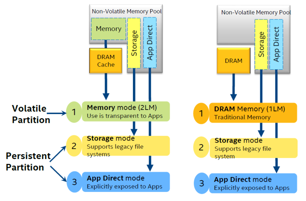
Figure 2 The different possible namespace partitions on the NVDIMMs (storage, space for Memory mode, and space for App Direct mode) and the way these partitions are visible to the OS and applications in the different platform modes.
The effect of the platform modes on NVDIMM usage can be further illustrated with an example: consider an NVDIMM where half of the persistent memory space is reserved for App Direct use, and half is reserved for use in Memory mode.
When booting the platform in Memory mode an application can see the full available NVRAM, but cannot see the DRAM. The DRAM is used as cache. The namespace reserved for App Direct needs to be made available by mounting it with a file system (see File Systems and Storage). This mode is illustrated in the diagram below, which shows a single NVDIMM (top) and DRAM DIMM (bottom).
When booting the platform in App direct mode, the NVDIMM namespace reserved for Memory mode usage is not visible to the application, and cannot be accessed. The App Direct reserved space on the NVDIMM functions as persistent memory (NVRAM). The DRAM is directly available to the application, and is used as regular, low-latency, memory. NVDIMM use in this mode is illustrated below.
Memory Configurations
There is a large number of possible configurations of the system, as different nodes can be set up with different uses of the NVRAM, and the space allocation on the NVDIMMs can be different as well. The main NVDIMM configuration used on the NextgenIO system is a mix of the two partitions, to avoid downtime due to node reboots following a switch in platform mode.
User control over the configuration in which the nodes are booted is described in the section on the Submitting Jobs.
Layout
A schematic overview of the NextgenIO system is shown in the diagram below. Access to the system is controlled via hydra-vpn, which connects to the system’s two login nodes. The 34 computing nodes (CN) are accessed via an Omnipath Switch (OPA 1), which also connects to the storage (SS1 and SS2).
Note that all MPI communication runs over a separate Omnipath network, which is controlled by a second switch (OPA 2).
The login and compute nodes nodes consist of 48 physical cores each. Hyperthreading doubles this number to 96 available logical cores per node.